Files are used as input and output when using TetGen as a stand-alone program. This section describes the input/output file formats of TetGen. When using TetGen as a library, the data structure tetgenio (explained in Section 6) is used to transfer the data stored in files.
In TetGen, a 3d PLC is described by a boundary discretization (e.g., a surface mesh) of the PLC. This description can be viewed as a Boundary Representation (B-Rep) without topological information, i.e., there are no information like incidences and orientations about edges and facets. This makes the description simple and it can describe non-manifolds easily. TetGen will recover and validate the topological information from this description during its meshing process.
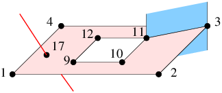
The boundary description of a PLC contains the set of vertices and facets of the PLC. Recall that each facet of a PLC is a 2d PLC. It may contain holes, segments and vertices in its interior, see Figure 19 for an example. TetGen describes a facet by a list of polygons and a list of holes. Each polygon of a facet is described by an ordered list of vertices. The order of the vertices can be in either clockwise or counterclockwise order. A polygon may be degenerate, i.e., it may contain only one or two vertices. A degenerate polygon is used to represent an isolated vertex or segment in this facet, see Fig. 19.
A hole in a facet is described by specifying an arbitrary point p ∈ ℝ3, such that the projection of p onto this facet lies strictly in the interior of this hole. Note that p is not a vertex of the PLC.
Remark. By the definition of a PLC, all vertices of a facet must lie in the same affine subspace of that facet. However, this requirement is generally impossible to be satisfied in practice due to the floating-point numbers used in computer. TetGen only requires that all vertices of a facet are approximately coplanar.
In addition, a list of holes and sub-regions of the PLC can be defined. A hole of the PLC is described by specifying an arbitrary point p ∈ ℝ3 that lies strictly in the interior of the hole. Sub-regions are described exactly the same way. Note that the points used to define holes and sub-regions are not vertices of the PLC.
This description of a PLC is further explained in the input file formats of TetGen, i.e., the .node, .poly, and .smesh file formats.
In TetGen, the mesh entities like vertices, edges, and faces, are assigned with a boundary marker. Boundary markers are tags (integers) used mainly to identify which entities are associated with which boundary element of the input PLC, such as, a segment or a facet. A common application is to determine where boundary conditions should be applied to a finite element mesh. You can prevent boundary markers from being written into files produced by TetGen by using the -B switch.
Mesh entities which are not on the boundary of the PLC must have the boundary markers ‘0’.
Mesh entities which are on the boundary will be assigned to a boundary marker that is the same as the boundary marker of that boundary of the PLC. However, if a boundary of a PLC does not have a boundary marker or have a marker ‘0’, TetGen will assign a ‘1’ to those entities belong to this boundary in the output files. This way, TetGen is able to distinguish them from other interior mesh entities.
Table 7 lists all file formats that are used by TetGen. All files are of ASCII form and may contain comments prefixed by the character ’#’. Points, tetrahedra, facets, edges, holes, and maximum volume constraints must be numbered consecutively, starting from either 1 or 0. However, all input files must be consistent. TetGen automatically detects your choice while reading the .node (or .poly or .smesh) file. When calling TetGen from another program, use the -z switch if you wish to number objects from zero.
.node input/output a list of nodes. .poly input a piecewise linear complex. .smesh input/output a piecewise linear complex. .ele input/output a list of tetrahedra. .face input/output a list of triangular faces. .edge input/output a list of edges. .vol input a list of maximum volumes. .mtr input/output a mesh sizing function. .var input a list of variant constraints. .neigh output a list of neighbors.
Table 7: Overview of TetGen’s file formats.
Remark: in the following description ‘#’ stands for ‘number’ – it should not cause confusion with the comment prefix.
A .node file contains a list of 3d points.
  First line:  <# of points> <dimension (3)> <# of attributes>
               <boundary markers (0 or 1)>
  Remaining lines list # of points:
    <point #> <x> <y> <z> [attributes] [boundary marker]
    ...
Each point has three coordinates (x, y and z), probably has one or several attributes, and a boundary marker as well. The .node files are used as both input and output files to represent the point set of a PLC, or the point set of a mesh, or the set of additional points (for the -i switch) which need to be inserted into a mesh. The example below demonstrates the layout of the .node file.
  # Node count, 3 dim, no attribute, no boundary marker
  8  3  0  0
  # Node index, node coordinates
  1  0.0 0.0 0.0
  2  1.0 0.0 0.0
  3  1.0 1.0 0.0
  4  0.0 1.0 0.0
  5  0.0 0.0 1.0
  6  1.0 0.0 1.0
  7  1.0 1.0 1.0
  8  0.0 1.0 1.0
The attributes, which are typically floating-point values of physical quantities (such as mass or conductivity) associated with the points, are copied unchanged to the output mesh.
If -p, -q, -a, or -i is selected, each Steiner point added to the mesh has attributes zero.
If the -w (weighted Delaunay tetrahedralization) switch is specified, the first attribute is regarded as the weight of that point.
If the <boundary marker> of the first line is 1, the last column of the remainder of the file is assumed to contain boundary markers. Boundary markers are used to identify boundary points (points resting on PLC facets). The .node file produced by TetGen contains boundary markers in the last column unless they are suppressed by the -B switch. The boundary marker associated with each point in an output .node file is chosen as follows:
TetGen can determine which points are on the boundary. Input with the boundary marker zero (or use no markers at all) will result in output with boundary marker 1 for all points on the boundary.
If the -R (mesh coarsening) switch is used, points with boundary markers equal to −1 will be removed.
A .poly file is a B-Rep description of a piecewise linear complex (PLC) containing some additional information. It consists of four parts.
The first three parts are mandatory, but the fourth part is optional. They are respectively described below.
Part 1 lists all the points, and is identical to the format of .node files. <# of points> may be set to zero to indicate that the points are listed in a separate .node file.
  First line:  <# of points> <dimension (3)> <# of attributes>
               <boundary markers (0 or 1)>
  Remaining lines list # of points:
    <point #> <x> <y> <z> [attributes] [boundary marker]
    ...
The facet list is given by
  One line: <# of facets> <boundary markers (0 or 1)>
  Following lines list # of facets:
     <facet #>
     ...
The format of a single facet is:
  One line: <# of polygons> [# of holes] [boundary marker]
  Following lines list # of polygons:
    <# of corners> <corner 1> <corner 2> ... <corner #>
    ...
  Following lines list # of holes:
    <hole #> <x> <y> <z>
    ...
Each facet is a polygonal region which may contain segments, single points and holes. It consists of a list of polygons. Each polygon is specified by giving the number of corners n, n ≥ 1, followed by the list of ordered indices of those corners. It does not matter which order (counterclockwise or clockwise) you choose to list the indices. It can be degenerate, i.e., n = 1 or n = 2 indicates a single point or a segment, respectively.
A hole in a facet is specified by identifying a point inside the hole. The list of hole points (consecutively) follows the list of polygons.
Boundary markers of facets are tags (integers) used mainly to identify which faces of the tetrahedralization are associated with which PLC facet, hence identify which faces occur on a boundary of the tetrahedralization. A common application is to use them to determine where different boundary condition types should be applied to a mesh.
If the [boundary marker] is 1, each facet is assumed to have a boundary marker (an integer). TetGen will produce an additional boundary marker for each face in the .face (output) file (in the last column of each record).
If the [boundary marker] is 0, TetGen will automatically assign a 1 to all boundary faces (which belong to facets of the PLC) in the .face (output) file.
You can prevent boundary markers from being written into the .face file by using the -B switch.
Note that each line of indices should not be arbitrarily long because the maximum characters per line read by TetGen is 1024. The list can be broken into several lines.
Holes in the volume are specified by identifying a point inside each hole.
  One line: <# of holes>
  Following lines list # of holes:
    <hole #> <x> <y> <z>
    ...
After the constrained Delaunay tetrahedralization is formed, TetGen creates holes by removing tetrahedra. This exactly is the reason that TetGen requires a closed boundary of the PLCs. In case of non-closed PLC facets the whole tetrahedralization will be “eaten" away. If two tetrahedra abutting a boundary face are removed, the boundary face itself is also vanished.
Hole points have to be placed inside a region, else the rounding error determines which side of the facet is being transformed into the hole.
The optional fourth section lists regional attributes (to be assigned to all tetrahedra in a region) and regional constraints on the maximum tetrahedron volume. TetGen will read this section only if the -A switch is used or the -a switch without a number is invoked. Regional attributes and volume constraints are propagated in the same manner as holes.
  One line: <# of region>
  Following lines list # of region attributes:
    <region #> <x> <y> <z> <region number> <region attribute>
    ...
If two values are written on a line after the x, y and z coordinate, the former is assumed to be a regional attribute (but will only be applied if the -A switch is selected), and the latter is assumed to be a regional volume constraint (but will only be applied if the -a switch is selected). It is possible to specify just one value after the coordinates. It can serve as both an attribute and a volume constraint, depending on the choice of switches. A negative maximum volume constraint allows to use the -A and the -a switches without imposing a volume constraint in this specific region.
In the following, a unit (1 × 1 × 1) cube is described by the poly file format.
  # Part 1 - node list
  # node count, 3 dim, no attribute, no boundary marker
  8  3  0  0
  # Node index, node coordinates
  1  0.0 0.0 0.0
  2  1.0 0.0 0.0
  3  1.0 1.0 0.0
  4  0.0 1.0 0.0
  5  0.0 0.0 1.0
  6  1.0 0.0 1.0
  7  1.0 1.0 1.0
  8  0.0 1.0 1.0

  # Part 2 - facet list
  # facet count, no boundary marker
  6  0
  # facets
  1            # 1 polygon, no hole, no boundary marker
  4  1 2 3 4   # front
  1
  4  5 6 7 8   # back
  1
  4  1 2 6 5   # bottom
  1
  4  2 3 7 6   # right
  1
  4  3 4 8 7   # top
  1
  4  4 1 5 8   # left

  # Part 3 - hole list
  0            # no hole

  # Part 4 - region list
  0            # no region
A .smesh file is also a B-Rep description of a PLC. It describes a simple B-Rep model where each of its facet only has exactly one polygon, no holes, no segment and no point inside. It is less flexible than the .poly file format, while it is much simpler and useful when the boundary of PLC consists of only simple polygons, i.e., triangles, quads, etc.
Analogously to the .poly file format, the .smesh file format consists of four parts, which are points, facets, holes and regions, respectively. Only the second part, which describes facets, is different. It is described below.
Each facet consists of exactly one polygon. The corner list of each polygon can be distributed over a number of lines. The optional boundary marker of each facet is given at the end of the corner list.
  One line: <# of facets> <boundary markers (0 or 1)>
  Following lines list # of facets:
    <# of corners> <corner 1> ... <corner #> [boundary marker]
    ...
The following example demonstrates the layout of the facet part of the unit cube.
  # Part 2 - facet list
  # facet count, no boundary marker
  6  0
  # facets
  4  1 2 3 4   # front
  4  5 6 7 8   # back
  4  1 2 6 5   # bottom
  4  2 3 7 6   # right
  4  3 4 8 7   # top
  4  4 1 5 8   # left
An .ele file contains a list of tetrahedra.
  First line: <# of tetrahedra> <nodes per tet. (4 or 10)>
              <region attribute (0 or 1)>
  Remaining lines list # of tetrahedra:
    <tetrahedron #> <node> <node> ... <node> [attribute]
    ...
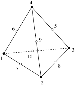
Each tetrahedron has four corners (or ten corners if the -o2 switch is used). Nodes are indices into the corresponding .node file. The first four nodes are the corner vertices. If -o2 switch is used, the remaining six nodes are generated on the midpoints of the edges of the tetrahedron. Figure 20 shows how these corners and the second-order nodes are locally numbered. Second order nodes are output only. They are omitted by the mesh reconstruction (the -r switch).
If the <region attribute> in the first line is 1, each tetrahedra has an additional region attribute (an integer) in the last column. Region attributes of tetrahedra are tags used mainly to identify which tetrahedra of the tetrahedralization are associated with which facet-bounded region (sub-domain) of the PLC, set in the fourth part of a .poly or a .smesh file. Region attributes do not diffuse across facets, all tetrahedra in the same region have exactly the same region attribute. A common application of the region attribute is to determine which material a tetrahedron has.
The .ele file is the default output file of TetGen. However, it can be omitted by -E switch. If -r switch is used, TetGen reads a .ele file and reconstructs a tetrahedral mesh from it.
The following example illustrates the layout of a .ele file.
  154  4  0
      1       4   107     3    50
      2       4   108     3   107
      3       9    97    95    94
      4       4   107    50    93
      5      56     1    50    47
      6      94    98    97    95
      7      97     9    95    55
      ...
A .face file contains a list of triangular faces of the tetrahedralization.
  First line: <# of faces> <boundary marker (0 or 1)>
  Remaining lines list # of faces:
    <face #> <node> <node> <node> ... [boundary marker] ...
    ...
In its basic form, each face has three corners and possibly has a boundary marker. Nodes are indices of the corresponding .node file.
If the <boundary marker> in the first line is 1, each face has an additional boundary marker (an integer) in the last column. Boundary markers of facets are defined in the .poly or the .smesh files. The optional column of boundary markers can be suppressed by the -B switch.
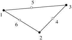
If the -o2 switch is used, each face has three corners and three second-order nodes generated on the midpoints of the edges of this face. Figure 21 shows the local numbering of the corners and the second-order nodes of a face. They are listed after the corners of this face, and before its boundary marker. Second order nodes are output only. They are ignored during the mesh reconstruction (the -r switch).
If the -nn switch is used, each face contains two additional indices (after the boundary marker) in the corresponding .ele file. They are indices of the tetrahedra containing this face. A −1 indicates that there is no adjacent tetrahedron at this side, i.e., it is “outer space".
TetGen default only outputs the boundary faces or the convex hull faces into a .face file. If the -f switch is used, TetGen outputs all faces (including interior faces) of the tetrahedralization. In this case, each interior face will always have a ‘0’ as its boundary marker. This file can be omitted by using the -F switch.
If the -r switch is used, TetGen can also read the .face file for identifying boundary faces in a reconstructed mesh.
An .edge file contains a list of edges of the tetrahedralization.
  First line: <# of edges> <boundary marker (0 or 1)>
  Remaining lines list # of edges:
    <edge #> <endpoint> <endpoint> ... [boundary marker] ...
    ...
In its basic form, each edge has two endpoints and possibly a boundary marker (if the <boundary marker> in the first line is 1). Endpoints are indices in the corresponding .node file.
If the -o2 switch is used, each edge has a second order node (its midpoint). It is listed after its endpoints, and before its boundary marker. Second order nodes are output only. They are ignored during the mesh reconstruction (the -r switch).
If the -nn switch is used, each edge contains one additional index (after the [boundary marker]) in the corresponding .ele file. It is the index of a tetrahedron which contain this edge. A −1 indicates that there is no tetrahedron containing this edge.
If the -r switch is used, TetGen can also read the .edge file for identifying boundary edges in a reconstructed mesh.
The .edge file is the default output of TetGen when -p or -r switch is used. By default, it only contains a list of boundary edges (segments) of the tetrahedralization. If the -e switch is used, it contains a list of all edges (including interior edges) of the tetrahedralization. The output of this file can be suppressed by the -F switch.
A .vol file associates with each tetrahedron a maximum volume that is used for mesh refinement. It is read by TetGen in case the -r switch is used.
  First line: <# of tetrahedra>
  Remaining lines list # of maximum volumes:
    <tetrahedron #> <maximum volume>
    ...
As with other file formats, every tetrahedron must be represented, and they must be numbered consecutively. A tetrahedron may be left unconstrained by assigning it a zero or negative maximum volume to it.
The .mtr file assigns a mesh sizing function defined on the nodes of an input PLC, or an input tetrahedral mesh, or a background tetrahedral mesh. It is used when the -m switch is applied.
  First line: <# of nodes> <size of metric (always 1)>
  Remaining lines list # of point metrics:
    <value>
    ...
Each node is assigned a value that is interpreted by TetGen as the desired length for all edges connecting to the node. TetGen uses this size information to generate an adaptive tetrahedral mesh.
Below is an example of an L-shaped PLC (L.smesh) (see Figure 17):
# L.smesh
12  3  0  0
1  0 0 0
2  4 0 0
3  4 2 0
4  2 2 0
5  2 6 0
6  0 6 0
1  0 0 2
2  4 0 2
3  4 2 2
4  2 2 2
5  2 6 2
6  0 6 2
8  0
6  1 2 3 4 5 6
6  7 8 9 10 11 12
4  1 2 8 7
4  2 3 9 8
4  3 4 10 9
4  4 5 11 10
4  5 6 12 11
4  6 1 7 12
0
0
Below is an example file L.mtr to assign a sizing function on the nodes of the PLC:
# L.mtr
12  1
0.25
0.25
0.25
0.025
0.25
0.25
0.25
0.25
0.25
0.025
0.25
0.25
The following command generates the adaptive tetrahedral mesh shown in Figure 17.
tetgen -pqm L.smesh
It is possible to set a size 0 to a node. In this case, TetGen ignores the mesh element size at this node. For example, it is possible to use an L.mtr file like the following;
# L.mtr
12  1
0
0
0
0.025
0
0
0
0
0
0.025
0
0
A .var file allows you to specify maximum area constraints on facets and maximum length constraints on segments. They are used for mesh refinement.
  One line: <# of facet constraints>
  Remaining lines list # of facet constraints:
    <constraint #> <boundary marker> <maximum area>
    ...
  One line: <# of segment constraints>
  Remaining lines list # of segment constraints:
    <constraint #> <point1> <point2> <maximum length>
    ...
A constraint of maximum area on facet is set by specifying the boundary marker of that facet, which is the integer assigned to that facet in the corresponding .poly or .smesh file. A constraint of maximum length on segment is set by specifying the indices of the two endpoints of that segment.
Figure 16 shows two examples of the results of applying constraints on a facet and a segment, respectively.
A .neigh file associates with each tetrahedron its neighbors (adjacent tetrahedra), which are indices in the corresponding .ele file.
  First line:  <# of tetrahedra>  4
  Following lines list # of neighbors:
    <tetrahedra #> <neighbor> <neighbor> <neighbor> <neighbor>
    ...
An index of −1 indicates no neighbor (because the tetrahedron is on boundary of a mesh domain). The first neighbor of the tetrahedron i is opposite to the first corner of tetrahedron i, and so on. The .neigh file is output by TetGen when the -n switch is used.
A .v.node file contains a list of vertices of the Voronoi diagram or the power diagram ( -w switch). Each Voronoi vertex is the circumcenter (or the orthocenter) of a Delaunay (or weighted Delaunay) tetrahedron. The format of .v.node is the same as that of a .node file.
A .v.edge file contains a list of edges of the Voronoi diagram or the power diagram ( -w switch). Each edge corresponds to a face of the Delaunay (or weighted Delaunay) tetrahedralization.
Each Voronoi edge is either a line segment connecting two Voronoi vertices or a ray starting from a Voronoi vertex. The file format of a .v.edge file is
  First line:  <# of edges>
  Following lines list # of edges:
    <edge #> <vertex 1> <vertex 2> <V_x> <V_y> <V_z>
    ...
<vertex 1> and <vertex 2> are two indices pointing to the list of Voronoi vertices. <vertex 1> must be non-negative, while <vertex 2> may be −1 which means it is a ray. In this case, the unit vector of this ray is given by <V_x>, <V_y>, and <V_z>.
A .v.face file contains a list of faces of the Voronoi diagram or the power diagram ( -w switch). Each face corresponds to an edge of the Delaunay (or weighted Delaunay) tetrahedralization. It is formed by a list of Voronoi edges, which may not be closed. The file format of a .v.face file is
  First line:  <# of faces>
  Following lines list # of faces:
    <face #> <cell 1> <cell 2> <# of edges> <edge 1> <edge 2> ...
    ...
<cell 1> and <cell 2> are two indices pointing into the list of Voronoi cells, i.e., the two cells share this face. <edge 1>, <edge 2> ..., are indices pointing into the edge list, i.e., they are the edges of this face, there are total <# of edges>. If the face is not closed, the index of the last edge of this face is −1.
A .v.cell file contains a list of cells of the Voronoi diagram or the power diagram ( -w switch). Each cell corresponds to a vertex of the Delaunay (or weighted Delaunay) tetrahedralization. A cell is formed by a list of Voronoi faces, which may not be closed. The file format of a .v.cell file is
  First line:  <# of cells>
  Following lines list # of cells:
    <cell #> <# of faces> <face 1> <face 2> ...
    ...
<face 1>, <face 2>, ... are indices pointing into the Voronoi face list. There are total <# of faces> faces. If the cell is not closed, the index of the last face in this cell is −1.
TetGen supports additional polyhedral file formats as well. Table 8 lists the supported file formats. TetGen recognizes the file formats by the file extensions.
.off input Geomview’s polyhedral file format. .ply input Polyhedral file format. .stl input Stereolithography format. .mesh input/output Medit’s mesh file format.
Table 8: Overview of supported file formats.
The .off is the one of the file formats of Geomview http://www.geomview.org - an interactive 3d viewing program for Unix/Linux. It represents collections of planar polygons with possibly shared vertices, a convenient way to describe polyhedra. The polygons may be concave, but there’s no provision for polygons containing holes.
The full description of the .off file format can be found elsewhere on the internet. Below is a simple description of this file format.
OFF numVertices numFaces numEdges
 x y z
 x y z
 ... numVertices like above
 NVertices v1 v2 v3 ... vN
 MVertices v1 v2 v3 ... vM
 ... numFaces like above
Note that vertices are numbered starting at 0 (not starting at 1), and that numEdges will always be zero.
The .ply file format is a simple object description that was designed as a convenient format for researchers who work with polygonal models. Early versions of this file format were used at Stanford University and at UNC Chapel Hill.
A description examples as well as codes of the PLY file format can be found at http://paulbourke.net/dataformats/ply/.
The .stl or stereolithography format is an ASCII or binary file used in manufacturing. It is a list of the triangular surfaces that describe a computer generated solid model. This is the standard input for most rapid prototyping machines.
The description of the .stl file format can be found elsewhere on the web. An elaborated description can be found at http://en.wikipedia.org/wiki/STL_(file_format). Below is an example.
solid
 ...

 facet normal 0.00 0.00 1.00
    outer loop
      vertex  2.00  2.00  0.00
      vertex -1.00  1.00  0.00
      vertex  0.00 -1.00  0.00
    endloop
  endfacet
 ...
 endsolid
The .mesh is the file formats of Medit - an interactive 3d mesh viewing program http://www.ann.jussieu.fr/frey/software.html. This file format is described in the documentation of Medit.
A repository of free 3d models in this file format are available at INRIA’s Free 3d Meshes Download http://www-roc.inria.fr/gamma/gamma/Accueil/.
This section provides three examples. They are designed to support interactive learning. The topics are describing PLCs using TetGen’s .poly file format and constructing different quality meshes through the command line switches.
Figure 22 shows the geometry of a rectangular bar. This bar consists of eight nodes and six facets (which are all rectangles). In addition, there are two boundary markers (−1 and −2) associated to the leftmost facet and the rightmost facet, respectively. This simple model has its physical meaning. It can be seen as the geometry of a typical heat transfer problem. The task is to compute the temperature diffusion in the bar, in which the flow of heat moves from the hot side to the cold side. The two boundary markers can represent two different boundary conditions, one has high temperature and the other has low temperature. Here is the input file bar.poly describing the bar:
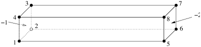
Figure 22: A bar having two boundary markers (−1 and −2) defined.
# Part 1 - the node list.
# A bar with 8 nodes in 3d, no attributes, no boundary marker.
8  3  0  0
  # The 4 leftmost nodes:
  1  0  0  0
  2  2  0  0
  3  2  2  0
  4  0  2  0
  # The 4 rightmost nodes:
  5  0  0  12
  6  2  0  12
  7  2  2  12
  8  0  2  12
# Part 2 - the facet list.
# Six facets with boundary markers.
6  1
  # The leftmost facet.
  1  0  -1   # 1 polygon, no hole, boundary marker (-1)
  4  1 2 3 4
  # The rightmost facet.
  1  0  -2   # 1 polygon, no hole, boundary marker (-2)
  4  5 6 7 8
  # Other facets.
  1
  4  1 5 6 2 # bottom side
  1
  4  2 6 7 3 # back side
  1
  4  3 7 8 4 # top side
  1
  4  4 8 5 1 # front side
# Part 3 - the hole list.
# There is no hole in bar.
0
# Part 4 - the region list.
# There is no region defined.
0
The command line is chosen as follows: first mesh the PLC (-p), then impose the quality constraint (-q). This will result in a quality mesh of four files: bar.1.node, bar.1.ele, bar.1.face, and bar.1.edge.
> tetgen -pq bar.poly
Here is the output file bar.1.node. It contains 47 points. The additional points were added by TetGen automatically to meet the quality measure.
47  3  0  0
   1    0  0  0
   2    2  0  0
   3    2  2  0
   4    0  2  0
   5    0  0  12
   6    2  0  12
   7    2  2  12
   8    0  2  12
   9    1.0000469999999999  0  0
  10    0  0.999668  0
  11    0  0.99944500000000003  12
  12    1.000594  0  12
  ...
# Generated by tetgen -pq bar.poly
Here is the output file bar.1.ele, which contains 83 tetrahedra.
83  4  0
    1      18    33    20    34
    2       9     2     3    25
    3      17    18    20    34
    4      43    32    18    37
    5      19    20    30    33
    6      14    41    13    42
    7      12    26     7     6
    8      10    28     1     9
    9      28    33    18    34
   10      35    41    38    45
   11      10     9    25    28
   12       3    25    19    30
   ...
# Generated by tetgen -pq bar.poly
Here is the output file bar.1.face with 90 boundary faces. Faces 1 and 2 are on the leftmost facet thus have markers −1; faces 3 and 4 have markers −2 indicating they are on the rightmost facet. Other faces have the default markers zero.
90  1
    1      3     4    10    -1
    2     10     9     3    -1
    3      7    12    11    -2
    4      7    11     8    -2
    5     18    37    43    0
    6     24    46    39    0
    7     26     6     7    0
    8     35    22    24    0
    9     29     7     8    0
   10     39     7    29    0
   11     29    11    27    0
   12     23    45    38    0
   ...
# Generated by tetgen -pq bar.poly
However, the mesh above may be too coarse for numerical simulation using finite element method or finite volume method. Using either the -q or the -a switch or both of them will result in a more dense quality mesh:
> tetgen -pq1.414a0.1 bar.poly
TetGen generates a mesh with 330 points and 1092 tetrahedra. The added points are due to both the -q and -a switches we have applied. To see a quality report of the mesh, type:
> tetgen -rNEFV bar.1.ele
In this example, we add an internal facet into the bar (in Figure 22), so that two sub-regions (separated by the newly added facet) in the bar are created. Figure 23 shows the modified geometry. This bar consists of twelve nodes (which I numbered) and seven facets (Note, some of them are not a single polygon any more). In addition, there are two regions defined, which have region attributes −10 and −20, respectively. Physically, you can associate two different materials to each of these two regions, and the two boundary markers (−1 and −2) in the last example still remain. Here is the input file bar2.poly describing the modified bar:
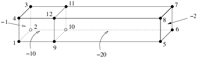
Figure 23: A bar having two regions (with region attributes −10 and −20, respectively) and two boundary markers (−1 and −2) defined.
# Part 1 - the node list.
# The model has 12 nodes in 3d, no attributes, no boundary marker.
12  3  0  0
  # The 4 leftmost nodes:
  1  0  0  0
  2  2  0  0
  3  2  2  0
  4  0  2  0
  # The 4 rightmost nodes:
  5  0  0  12
  6  2  0  12
  7  2  2  12
  8  0  2  12
  # The 4 added nodes:
  9  0  0  3
  10 2  0  3
  11 2  2  3
  12 0  2  3
# Part 2 - the facet list.
# Seven facets with boundary markers.
7  1
  # The leftmost facet.
  1  0  -1   # 1 polygon, no hole, boundary marker (-1)
  4  1 2 3 4
  # The rightmost facet.
  1  0  -2   # 1 polygon, no hole, boundary marker (-2)
  4  5 6 7 8
  # Each of following facets has two polygons, which are
  # one rectangle (6 corners) and one segment.
  2
  6  1 9 5 6 10 2 # bottom side
  2  9 10
  2
  6  2 10 6 7 11 3 # back side
  2  10 11
  2
  6  3 11 7 8 12 4 # top side
  2  11 12
  2
  6  4 12 8 5 9 1 # front side
  2  12 9
  # The internal facet separates two regions.
  1
  4  9 10 11 12
# Part 3 - the hole list.
# There is no hole in bar.
0
# Part 4 - the region list.
# There are two regions (-10 and -20) defined.
2
  1  1.0 1.0 1.5  -10  0.1
  2  1.0 1.0 5.0  -20  -1
The command line tetgen -pqaA bar2.poly generates the file bar2.1.ele. The first eight lines are listed next. It differs from bar.1.ele in that each record has an additional region attribute.
431  4  1
    1      32    57    50    60    -20
    2      51    23    50    49    -20
    3      88   138   116   149    -10
    4      76    96    95    36    -20
    5      29    55    56    52    -20
    6     132   138    88   139    -10
    7      65   138   132   139    -10
    8      16    54    53    15    -20
    ...
# Generated by tetgen -pqaA bar2.poly
Visualization of the resulting meshes (by TetView or other tools) shows that the refinement in the region with attribute −10 is denser than in that with −20. This is due to the volume constraints, (0.1) defined in the file bar2.poly, and due to the -aA switches.
This is the example file (example.poly) coming together with the TetGen’s source distribution. The geometry as well as some generated mesh are shown in Figure 24.
# Part 1 - the node list.
28  3  0  1
1  0  0  0  1
2  2  0  0  1
3  2  2  0  1
4  0  2  0  1
5  0  0  4  9
6  2  0  4  9
7  2  2  3  9
8  0  2  3  9
9  0  0  5  2
10  2  0  5  2
11  2  2  5  2
12  0  2  5  2
13  0.25  0.25  0.5  4
14  1.75  0.25  0.5  4
15  1.75  1.5  0.5  4
16  0.25  1.5  0.5  4
17  0.25  0.25  1  4
18  1.75  0.25  1  4
19  1.75  1.5  1  4
20  0.25  1.5  1  4
21  0.25  0  2  4
22  1.75  0  2  4
23  1.75  1.5  2  4
24  0.25  1.5  2  4
25  0.25  0  2.5  4
26  1.75  0  2.5  4
27  1.75  1.5  2.5  4
28  0.25  1.5  2.5  4
# Part 2 - the facet list
23  1
1  0  1  # 1
4    1  2  3  4
1  0  9  # 2
4    5  6  7  8
2  1  3  # 3
4    1  2  6  5
4    21  22  26  25
1  1  0  2.25
1  0  3  # 4
4    2  3  7  6
1  0  3  # 5
4    3  4  8  7
1  0  3  # 6
4    4  1  5  8
1  0  2  # 7
4    9  10  11  12
1  0  3  # 8
4    9  10  6  5
1  0  3  # 9
4    10  11  7  6
1  0  3  # 10
4    11  12  8  7
1  0  3  # 11
4    12  9  5  8
1  0  4  # 12
4    13  14  15  16
1  0  4  # 13
4    17  18  19  20
1  0  4  # 14
4    13  14  18  17
1  0  4  # 15
4    14  15  19  18
1  0  4  # 16
4    15  16  20  19
1  0  4  # 17
4    16  13  17  20
1  0  4  # 18
4    21  22  23  24
1  0  4  # 19
4    25  26  27  28
1  0  4  # 20
4    21  22  26  25
1  0  4  # 21
4    22  23  27  26
1  0  4  # 22
4    23  24  28  27
1  0  4  # 23
4    24  21  25  28
# Part 3 - the hole list
2
1  1  0.4  2.25
2  1  0.4  0.75
# Part 4 - the region list
2
1  1  0.25  0.1  10  0.001
2  1  0.5  4  20  0.01
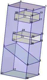
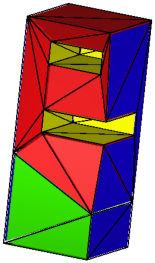
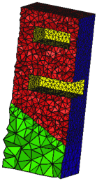
Figure 24: Left: A PLC with two sub-regions (materials) and two holes. Middle: the CDT generated by the command line: -pA. Right: The quality tetrahedral mesh generated by the command line: -pqAa.